Getting a good clean signal over the serial port was really important. After a fair bit of use of the acrylic laser cut connect, it was found that it constituted too much trial and error in manually making the connection. So the idea to actually modify the Palm serial port into a connector started to take root. The key idea is to look for a space on the Palm, solder the connector and have that connected permanently on the Palm, so that when required, an add-on board can be used to expand the capability of the unit, instead of mucking around with the 10-pin port.
Opening the Palm, Soldering the pins
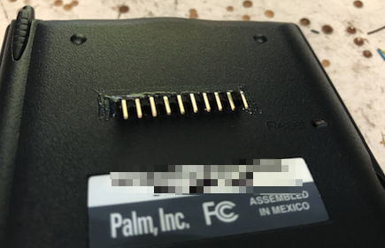
Opening the palm was easy. I followed a post from iFixit to get that done. It was then decided to put the pin connectors on the flat portion at the back of the Palm. The PCB at that area was also empty giving me space to work the wires. I used an isolating tape to mask off the areas where the 10-pin was frequently used by external accessories and soldered “backward” the wires that would extend to the connecting pins.
The wires are then routed internally along the edge gaps of the palm and soldered underneath the cover.
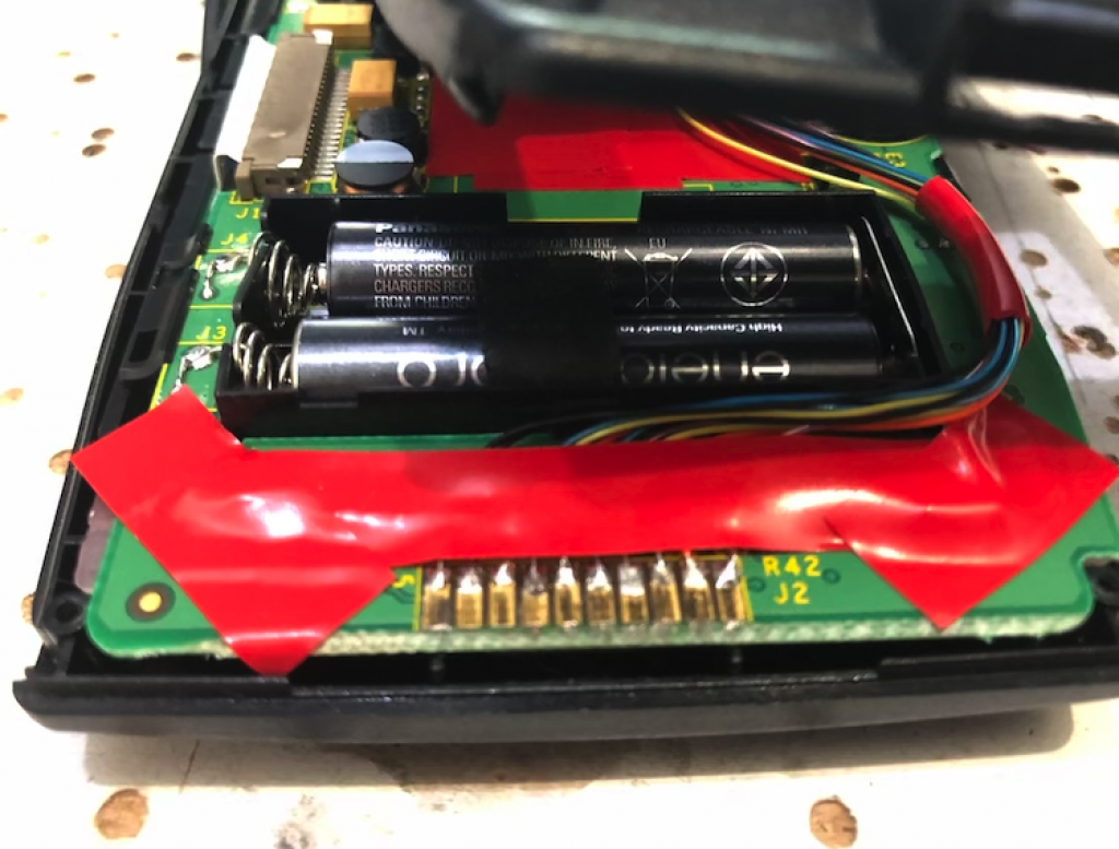
On the PCB, insulating tape was also used on the PCB to prevent short circuits just incase the pins were to touch and scratch the board.
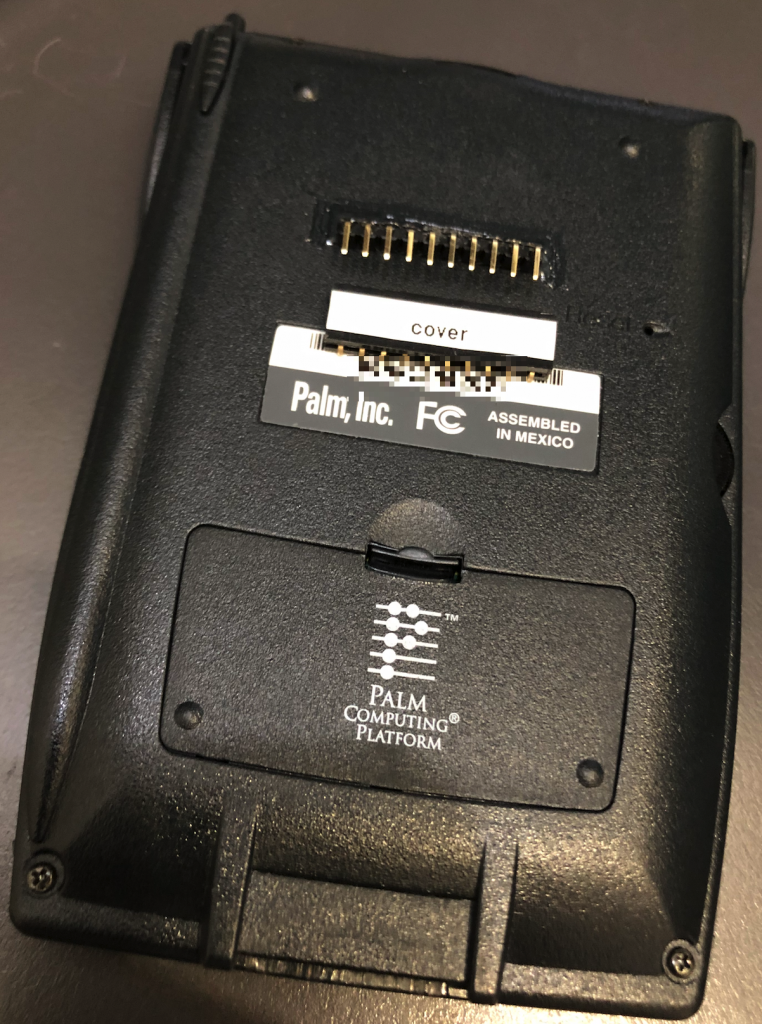
All these are then carefully re-assembled, hiding all the wires within the Palm. The end result is a neat package with no visible modifications to the 10-pin port.
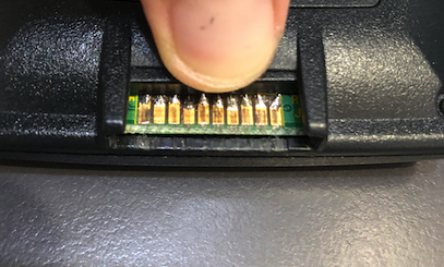
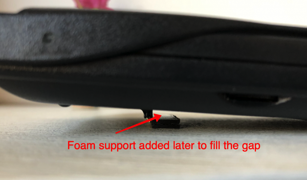
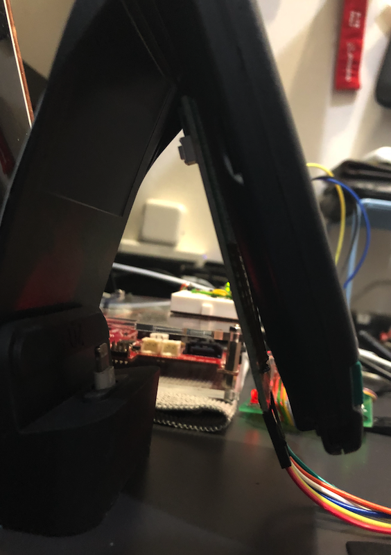
The exposed pins shows up on the back, providing a slight improvement in viewing angle when placed flat on a table top. A cover was made to provide some amount of protection to the pins, but I have found that is usually unnecessary.
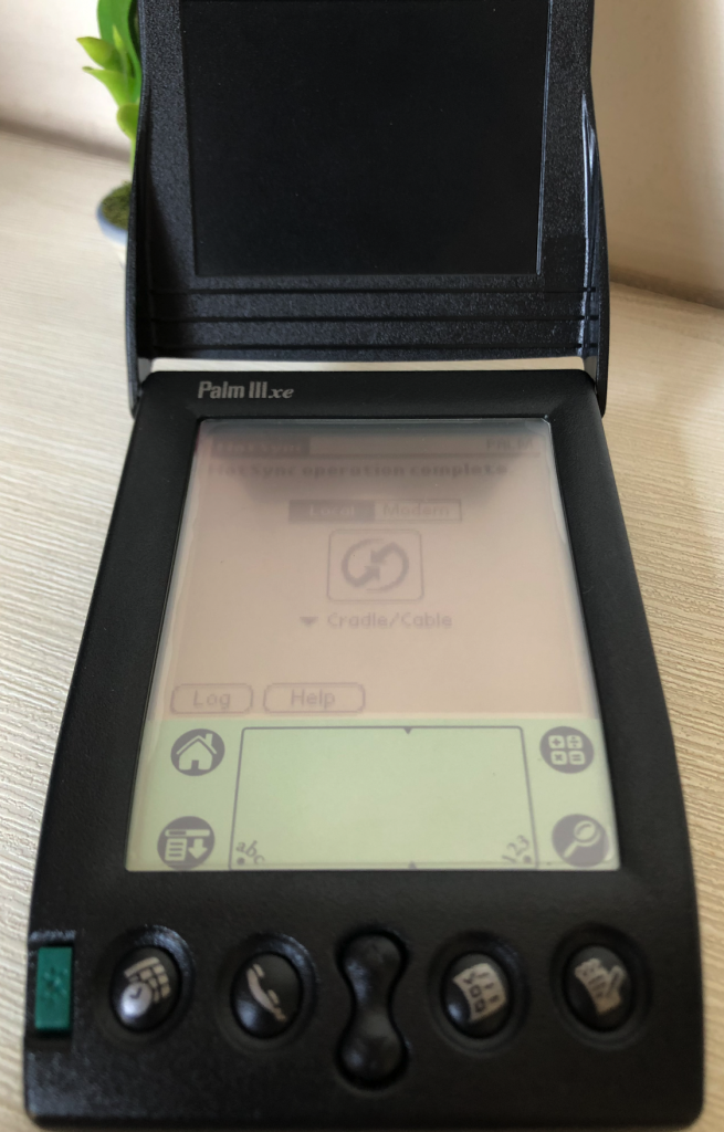
Upon re-assembly, a functional check was done to ensure that everything is still working…. and it is.. yeah!
Connecting an Expansion Board
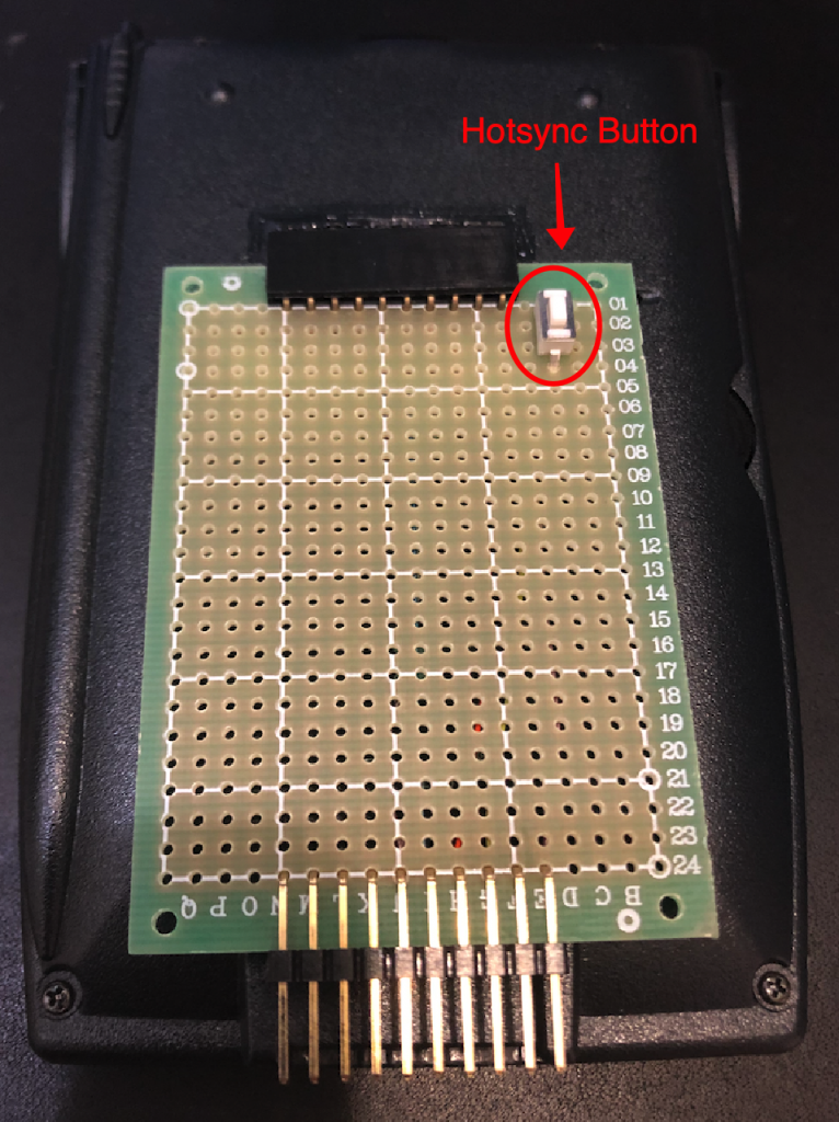
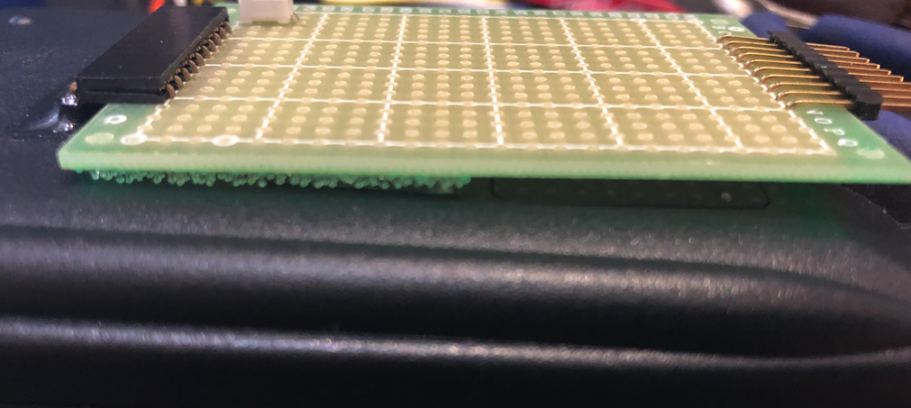
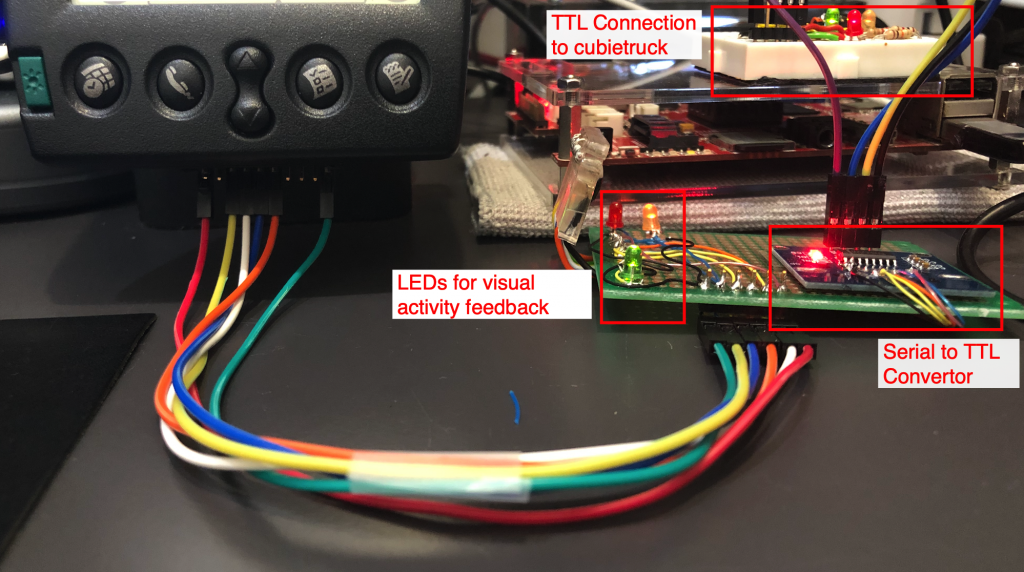
The connector pins lines itself up to a 5x7cm DIY PCB. The connection is fairly straightforward and acts as a breakout board for additional functions like the adding a Hotsync button. Jumper wires are used to extend and connect the various pins to additional circuitry making it a lot neater to deal with. Some pictures below to illustrate what was done. Overall, it wasn’t rocket science, but it surely made the connections a lot easier to deal with.
Conclusion
All the above and previous work finally made sure that I was able to have a good way to achieve a “break-out” of the palm pilot pins unto a PCB which I can then work on. This made it a lot simpler to connect things like resistors and other ICs. As noted in Part 1, this kinda fixed issue 3-6. But now I have to begin working on question (3)…. how do I get the baud rate past 19200? And why can’t I get PPP working? All that experimentation would be detailed in another post.